Technology and products

District heating production units (Principle)

Projecting

The entire plant is designed in 3D. In the cases that more entrepreneurs collaborates the respectives design merges to a joint 3D-layout.

Balance of Plant

Fuel storage and fuel handling

Fuel store

Fuel, consisting of a flammable fraction of household and industrial waste or biofuel, comes to the facility in rearward or side-dumping vehicles. The fuel is unloaded into the receiving bin.

The fuel store is of the overhead crane system type. The clamshell bucket is used to both unload into the fuel store and to feed the boiler bin. The clamshell bucket crane is fully automated, but can also be operated from an operator seat in the control room.

Technical data

Fuel store volume approx 3,500 m3
Receiving bin volume approx 800 m3

Ash and cinder processing unit

The unit is designed so that all cinders, bottom ash and roaster fall-through is remoisturised and then transported and deposited in the ash and cinder room with a trash transporter constructed by ETK.

Furnace and Boiler

Furnace for combustion of household and industrial waste or biofuel with temperatures and wait times in compliance with European standards. Water pipe boiler for generation of overheated steam for electricity and district heating production.

Steam Turbine Unit

Steam turbine unit with corresponding condenser unit for generating electricity and district heating with an alpha value over 20%.

Exhaust Gas Purification

Exhaust gas purification unit for purifying exhaust gas with emissions in compliance with European standards.

Pipe Technology Unit

The pipe technology unit is divided into 3 subunits.

  • Steam system
  • District heating circuit
  • Service pipe system, cold and hot waterÅngsystem
Steam System

Complete steam system from boiler to turbine/condenser and via feed water tank and pumps back to the boiler.

District heating circuit

The district heating system from the condenser ends with the valve and the pipe to the inside boiler wall.

Service pipe system

Cold water supply, fire hydrants, instruments and compressed air.

Electric Power To The Unit

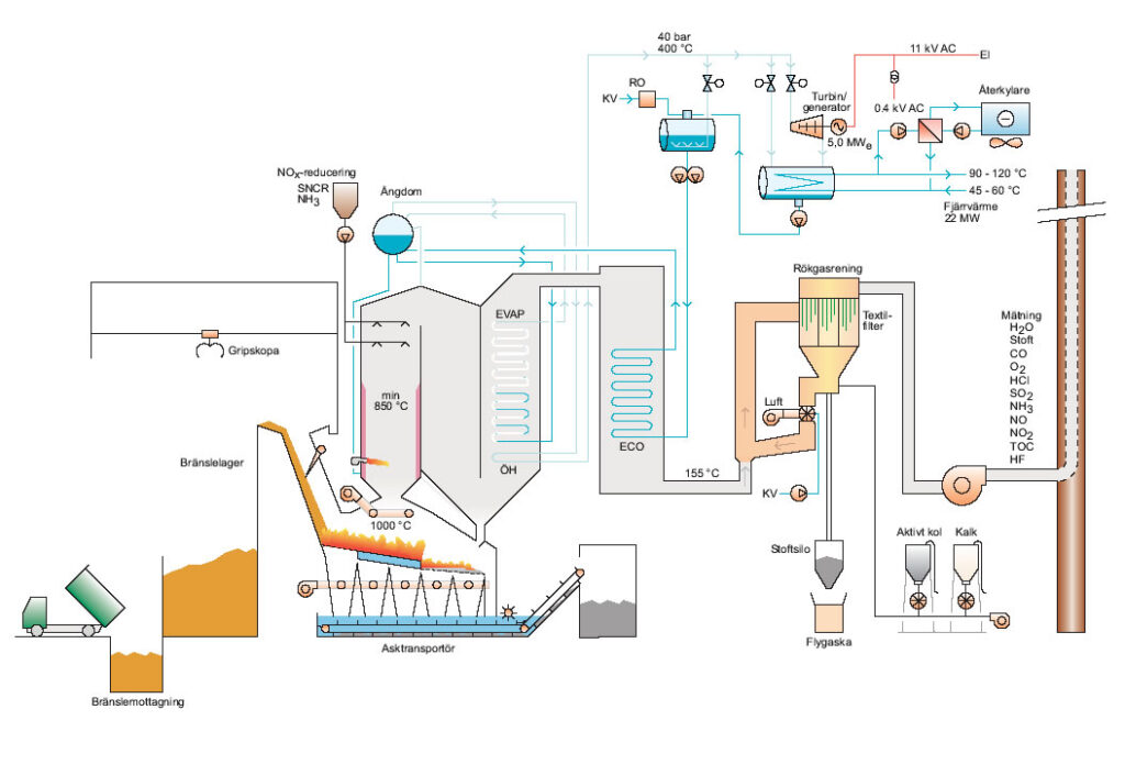
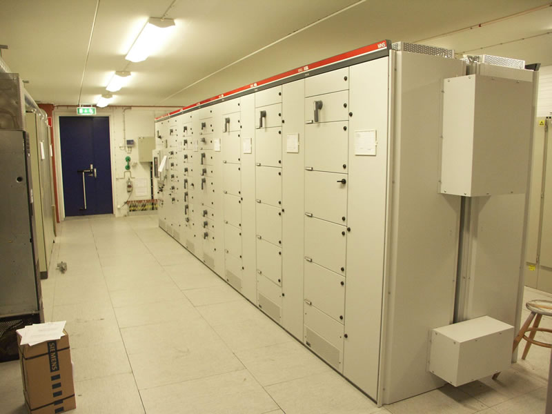
The unit is supplied electricity from an intermediate voltage switching station (11 kV) via transformers 11/0.4 kV to a low voltage switching station with removable motor groups. Frequency converter to all large motor groups.

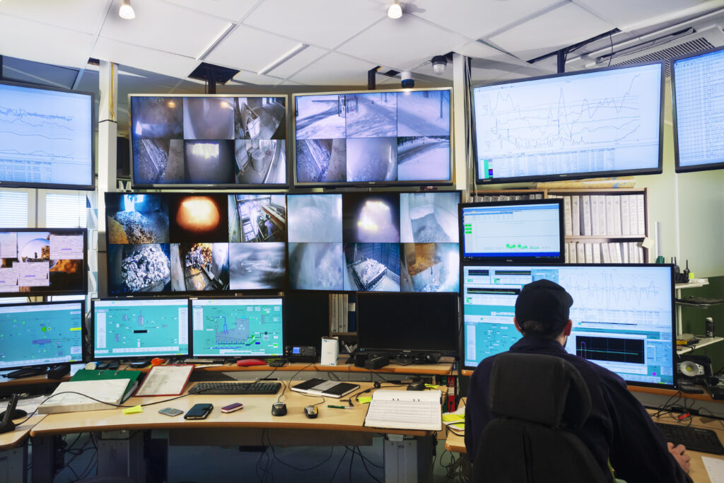
Interruption-free power supply system of type UPS for control system, safety functions, information system and alarm system.

Fully automatic backup power system

Complete wiring, including cable runs, work switch, coupling boxes for entire unit manufactured in compliance with specified standard and regulations. Earth fault monitoring and potential earthing.

Control and Monitoring System

Control system of type DCS.
The unit contains a control system for each subunit as follows:

  • Boiler
  • Other equipment
  • Overhead cranes

The whole plant is operated from the controlroom.